Autel XP400 is powerful Chip and Key Programmer, which need to work with Autel MaxiIM IM608/IM508. Autel Xp400 support Read/Write Vehicle Transponder Chip Data, including Benz Infrared Keys, Generate Vehicle-specific Keys and Dealers’Key;Read ECU Data, including EEPROM and MCU;and Read/Write Vehicle Keys and Remotes Data.

Autel XP400 Device Detail Introduction:
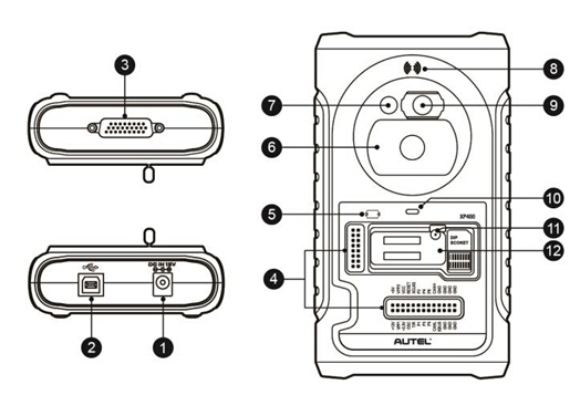
1. DC Port – provides 12V DC power supply.
2. USB Port – provides data communication and 5V DC power supply.
3. DB 26-Pin Port – connects with the Mercedes Benz infrared cable, vehicle key cable, ECU cable, MCU cable, MC9S12 cable.
4. Cross Signal Pins – holds the MCU board, MCU spare cable or DIY signal interface.
5. IC Card Induction Area
6. Vehicle Key Slot – holds the vehicle key.
7. Transponder Slot – holds the transponder.
8. Remote Control Transponder Induction Area Figure 2-5 XP400 Views 11
9. Mercedes Infrared Key Slot – holds the Mercedes infrared key.
10. Status LED – indicates the current operating status.
11. Locker – locks the EEPROM component transponder slot to ensure proper functioning.
12. EEPROM Component Transponder Slot – holds the EEPROM plug-in transponder or EEPROM socket.
2.1 USB Port
Type B USB port is used for data communication and USB power supply of tablet device, ATProgrammer on PC and XP400 Super Programmer.
2.2 DC Port
DC interface is used to provide 12V DC power supply for XP400 Super Programmer
2.3 DB 26-Pin Port
The port can connect with four components: ECU cable, MCU cable, MC9S12 cable, and Benz infrared cable (encapsulated interface, no cable definition).
Table 1. ECU Cable Definition
| No. | Color | Definition | Pin Position Corresponding to DB26 | Remark |
| 1 | Red | VCC12V | 7 | |
| 2 | Black | GND | 10/25 | |
| 3 | Green | IGN | 14 | |
| 4 | Orange | CANL | 8 | |
| 5 | Blue | CANH | 17 | |
| 6 | Brown | BOOTM | / | |
| 7 | Yellow | K | 18 | |
| 8 | White | LIN | 26 |
Table 2. MCU Cable Definition
| No. | Color | Definition | Pin Position Corresponding to DB26 | Remark |
| 1 | Red and Black | VPP2 | 12 | |
| 2 | Red and Yellow | VCC12V | 7 | |
| 3 | Red and Blue | VPPR | 20 | |
| 4 | Red and White | VPP1 | 20 | |
| 5 | Black | GND | 25 | |
| 6 | Gray | S3 | 23 | |
| 7 | Green | S9 | 2 | |
| 8 | Blue | S4 | 11 | |
| 9 | White | S1 | 14 | |
| 10 | Purple | S7 | 4 | |
| 11 | Orange | S6 | 13 | |
| 12 | Yellow | S8 | 19 | |
| 13 | Red | S5 | 21 | |
| 14 | Brown | S2 | 5 | |
| 15 | White and Green | S10 | 9 | |
| 17 | Black | GND | 10 | Shielded Twisted Pair |
| 18 | White | OSC | 1 | Shielded Twisted Pair |
Table 3. MC9S12 Cable Definition
| No. | Color | Definition | Pin Position Corresponding to DB26 | Remark |
| 1 | Red | VCC5V | 16 | |
| 2 | Black | GND | 10/25 | |
| 3 | Green | XCLKS | 2 | |
| 4 | Blue | T/R | 11 | |
| 5 | Yellow | RESET | 19 | |
| 6 | Black | GND | 10 | Shielded Twisted Pair |
| 7 | White | OSC | 1 | Shielded Twisted Pair |
2.1 Cross Signal Pin
Used to hold external MCU spare cable or DIY signal connection cable for reading and writing special MCU and ECU chip.
2.2 Vehicle Key Slot
Used to hold a variety of vehicle keys for reading and writing vehicle key information.
2.3 Transponder Slot
Used to hold a variety of transponders for reading and writing transponder information.
2.4 Benz Infrared Key Slot
Used to hold Benz infrared transponder for reading and writing Benz infrared transponder information.
2.5 Status Indicator Lamp
The status indicator lamp is used to display the current operating status of the XP400 Super Programmer. The statuses of the indicators are as follows
Table 5. Description of Status Indicator Lamp
| Bi-color Lamp | Status | Description |
| Indicator lamp | Solid green | Normal power supply |
| Flashing green | Working | |
| Solid red / yellow | Fault |
2.6 Locker
Used to hold EEPROM plug-in chip, or EEPROM socket (SOP8 chip placed in the socket) for reading and writing EEPROM data.
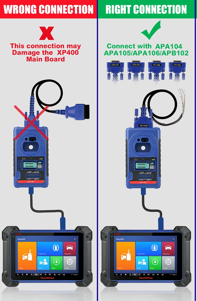
Autel XP400 Connection:
Autel XP400 Software Download and Update:
Autel XP400 ATProgrammer Software Download and Firmware Update
Autel XP400 vs XP400 Pro vs VVDI PROG:
| Feature | XP400 | XP400 PRO | VVDI PROG |
| EEPROM re*d/write — MCU raad/write | 330 chip types _ 1541 chip types | 445 different chip types newly added support (AM29FXXX series. MB29FXXX fries) 2067 chip types | 429 different chip types |
| 7S8 different chip types | |||
| Enflne ECU read/write | 40 chip types | 41 chip types Xd write support for SIMTEC76(AM29F8OOBB).WRITE | fngine ECU read (74 types) |
| mmobiliitr ECU etd/write | 168 chip types | 181 chip types | 171 chip typw |
| Odometer read/write | read odometer module 9 types | eX odometer module 171 tvpe$(update in July) | ead odometer module 171 types |
| Airb«g re*d/write | re*d airbag module 5 types | ead airbag module 5 types | eX airbag module 54 types |
| Frequency (tettctlon Key read/wnte | 31S/433/868MHZ | 315/433/868MHZ | N/A |
| support | support | N/A | |
| Unlock key | N/A | support 11 key type$(Audi/BMW| ‘… – | 6 key types |
| Writ# key 5* dump | Mitsubishi, Suzuki, fiat, jndroverjugu^r | Mitsubishi, Suzuki, Fiat, Undrover, Juguar | Support 40*vthkle maken |
| Easy to uK/sUbllltv | l.menus are too value and can’t select intuitively I. with high<definition wiring dkigram$(no< sufficiently coveredl | l.Stability of key read/write, chip read/write, IR key read/write are greatly enhanced. menus are too vague and can’t select intuitively 3 with high definition wiring diagram$(not wffkwntly covered) | I. menus are clear and e«y to k with high definition wiring d<agfam$(wmciently covered) J. high stability of chip read/write |
Download: Autel XP400 User Manual